
Note: To prepare your network for use with the XV Gateway, refer to the DMP Port Compatibility Guide.
The XV Gateway (XV-24, XV-60, XV-96) with AlarmVision® seamlessly integrates cameras, analytics, and the XR Series or XT75 Control Panel to create smart motion detectors that trigger panel responses in real time based on real events for real results.
Virtual Keypad users can view live and recorded HD video clips, define video actions, and receive push notifications of real events in real time for real results.
Note: You need an active Dealer Admin account at dealer.securecomwireless.com to activate the XV Gateway.
The primary network connection on the XV Gateway and the panel should be connected to the same network switch. You can also use any network switch that is connected to the same subnet that the panel is connected to.
Note: The HDMI port does not support an external display of camera streams on the XV-24, XV-60, or XV-96.
Using a Network Switch
-
Connect a network cable from the panel to a network switch.
-
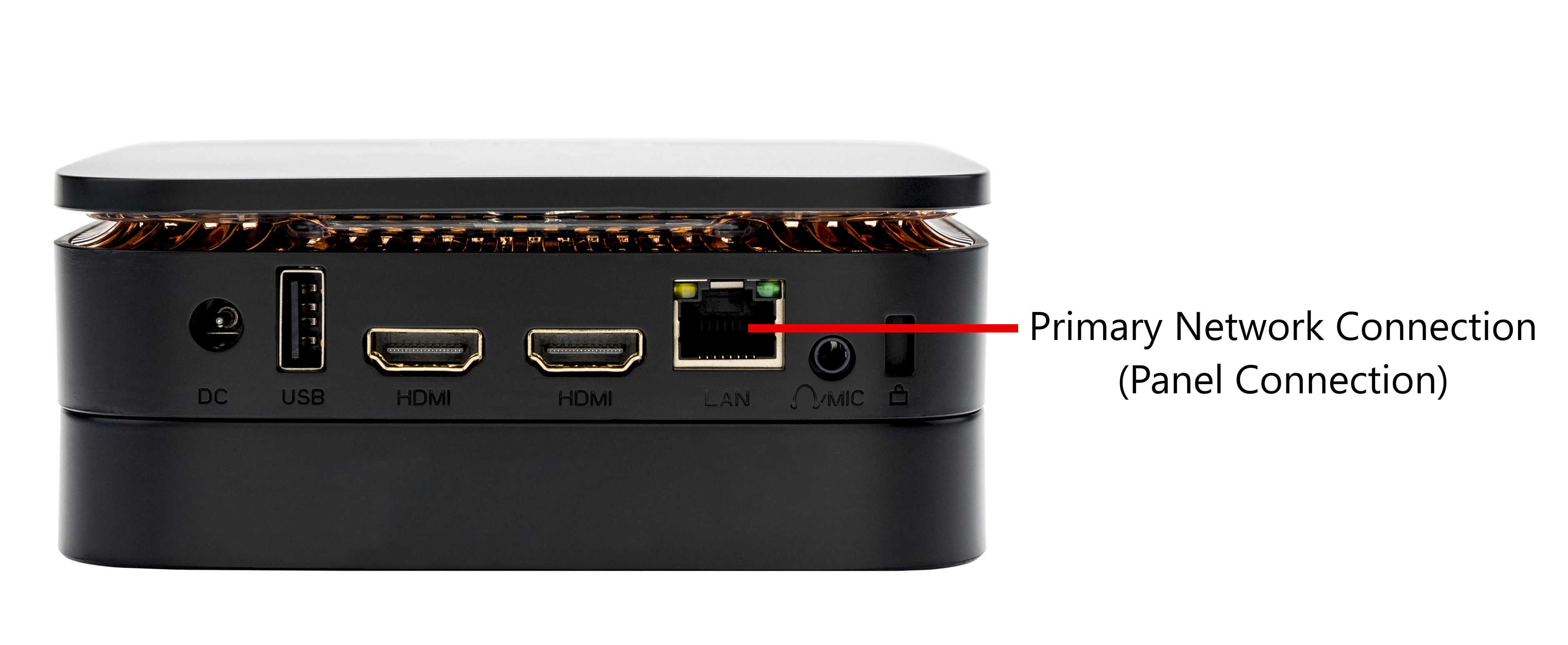
Connect a network cable from the XV Gateway’s primary network connector, located on the back of the device, to the same network switch that the panel is connected to. This ensures that both the panel and the XV Gateway communicate over the same network.
Using the Same Subnet
-
Connect a network cable from the panel to a network switch.
-
If the XV Gateway cannot be connected to the same network switch that the panel is connected to, you can use any network switch that is connected to the same subnet the panel is connected to.
Using Dual NIC
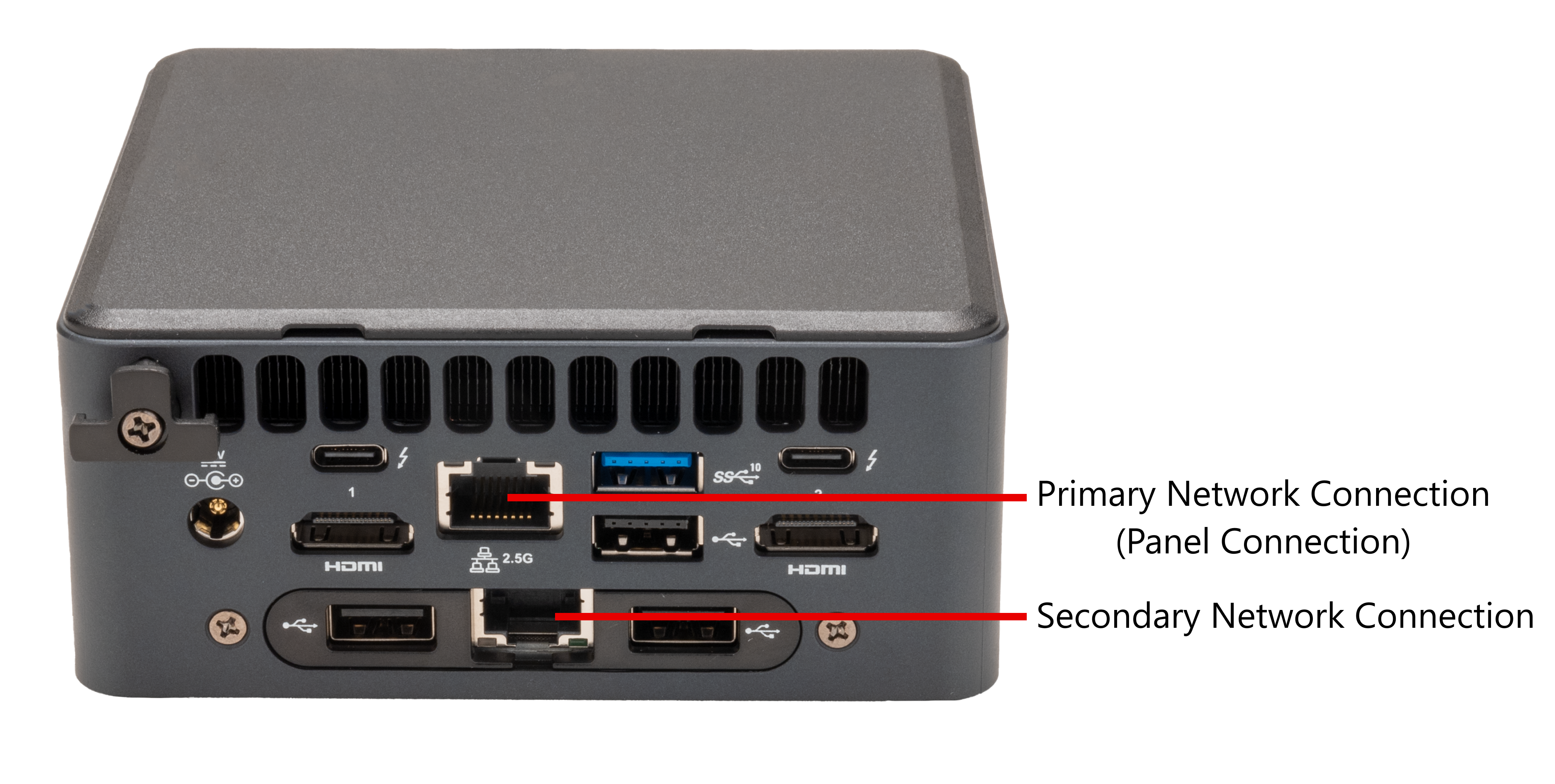
If you are using a secondary NIC at initial installation, connect the secondary network connection on the XV-60 or XV-96 prior to adding the XV Gateway on Dealer Admin. Ensure the primary network connection is also connected to the XV Gateway.
Refer to Configure Secondary NIC for Private Camera Network for more information.
Note: The panel can only be connected to the primary network connection through the network switch or subnet.
Additional Information
XV Gateway Models
XV-24: 24 MP Video Analytics-Enabled Motion Detector
XV-60: 60 MP Video Analytics-Enabled Motion Detector
XV-96: 96 MP Video Analytics-Enabled Motion Detector
Certifications
NDAA Compliant
Specifications
Supports ONVIF and RTSP cameras
One TB internal storage (XV-24)
Four TB internal storages (XV-60 and XV-96)
Up to 24, 60, or 96 MP Processing
Includes Power Supply